

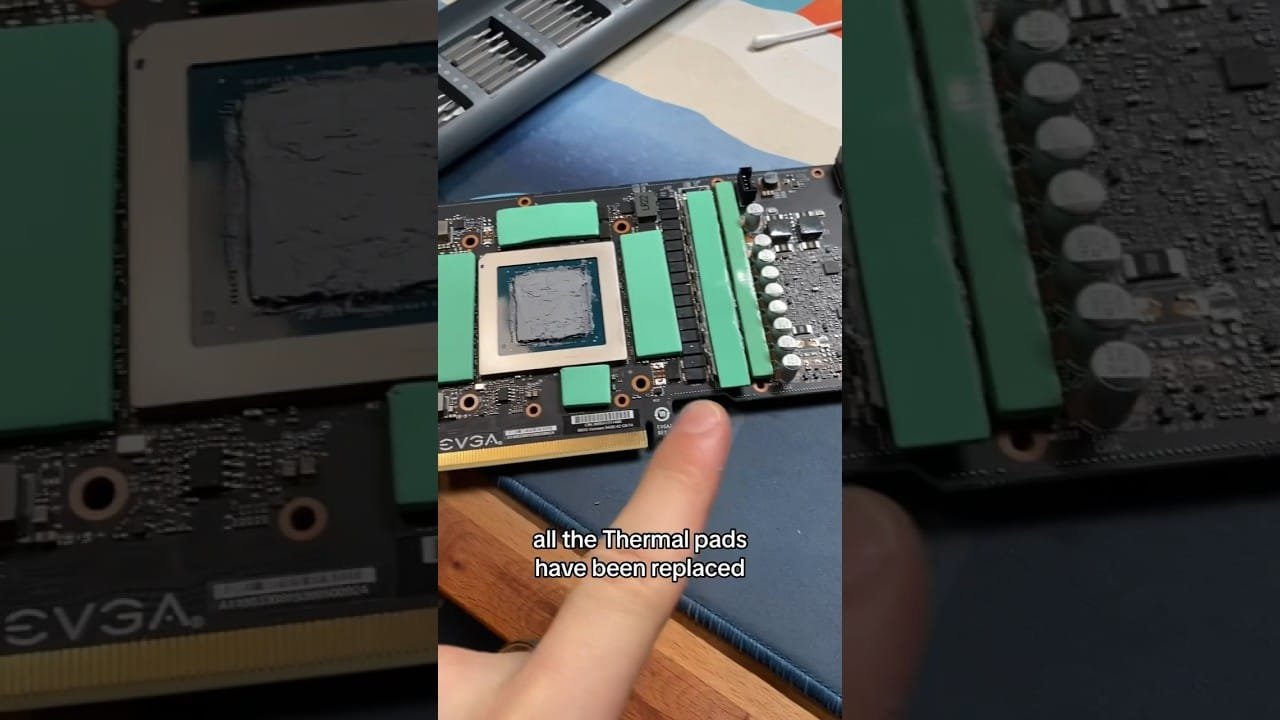
A GPU Hotspot Temperature spike is a common issue that can disrupt your device performance. If you are experiencing a GPU Hotspot Temperature problem, this 2026 step-by-step diagnostic guide will help you troubleshoot and resolve the problem quickly.
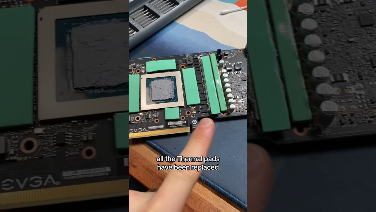
Table of Contents
Quick Overview: GPU Thermal Delta Explained
Modern graphics processing units monitor hardware thermals using an array of sensors embedded across the silicon die. Consequently, software utilities like HWInfo64 report two primary readings: overall GPU core temperature and hotspot temperature.
Specifically, core temperature measures the weighted average across the die, whereas the hotspot reading targets the absolute hottest single sensor located near compute units or memory controllers. Therefore, high temperature spikes indicate localized thermal contact failure rather than complete cooler failure.
Understanding Your GPU Hotspot Temperature
Before implementing fixes, monitoring your GPU Hotspot Temperature is crucial for establishing baseline diagnostic parameters under real-time gaming or synthetic rendering workloads.
Under standard operating conditions, the difference between core thermals and hotspot thermals ranges between 12°C and 18°C. However, when this delta expands past 25°C, thermal paste degradation, pump-out effect, or mounting bracket torque loss has occurred. For example, a core reading of 68°C alongside a hotspot reading of 106°C signals an emergency cooling disparity.
In addition, persistent hotspot temperatures above 105°C trigger safety mechanisms designed to protect silicon. Consequently, your graphics card will throttle clock frequencies dramatically, resulting in sudden frame stuttering, fan noise ramps, or black screen system crashes. If your cooling fans spin aggressively to counteract this, read our guide on GPU Fan Spinning Fast troubleshooting for targeted acoustic fixes.
Diagnostic Comparison: Hotspot vs Core Temperature
Evaluating thermal disparity requires systematic monitoring under uniform stress testing environments such as FurMark or 3DMark Time Spy. The diagnostic table below outlines typical operational ranges and recommended remediation steps.
| Hotspot Delta | Hotspot Range | Thermal Status | Required Action |
|---|---|---|---|
| 10°C – 15°C | 65°C – 80°C | Optimal Operating Condition | No maintenance required. Maintain normal cleaning cycles. |
| 16°C – 22°C | 81°C – 94°C | Acceptable Under Heavy Load | Adjust fan curves and clear dust filters in PC case. |
| 23°C – 30°C | 95°C – 104°C | Elevated / Micro-Throttling | Apply undervolt settings; schedule thermal paste replacement. |
| 30°C+ | 105°C – 115°C+ | Critical Thermal Throttling | Immediate repaste, check mounting torque, replace phase-change pads. |
Step-by-Step GPU Hotspot Temperature Fixes
Resolving thermal bottlenecks requires methodical isolation of hardware and airflow variables. Follow these sequential steps to safely lower heat output.
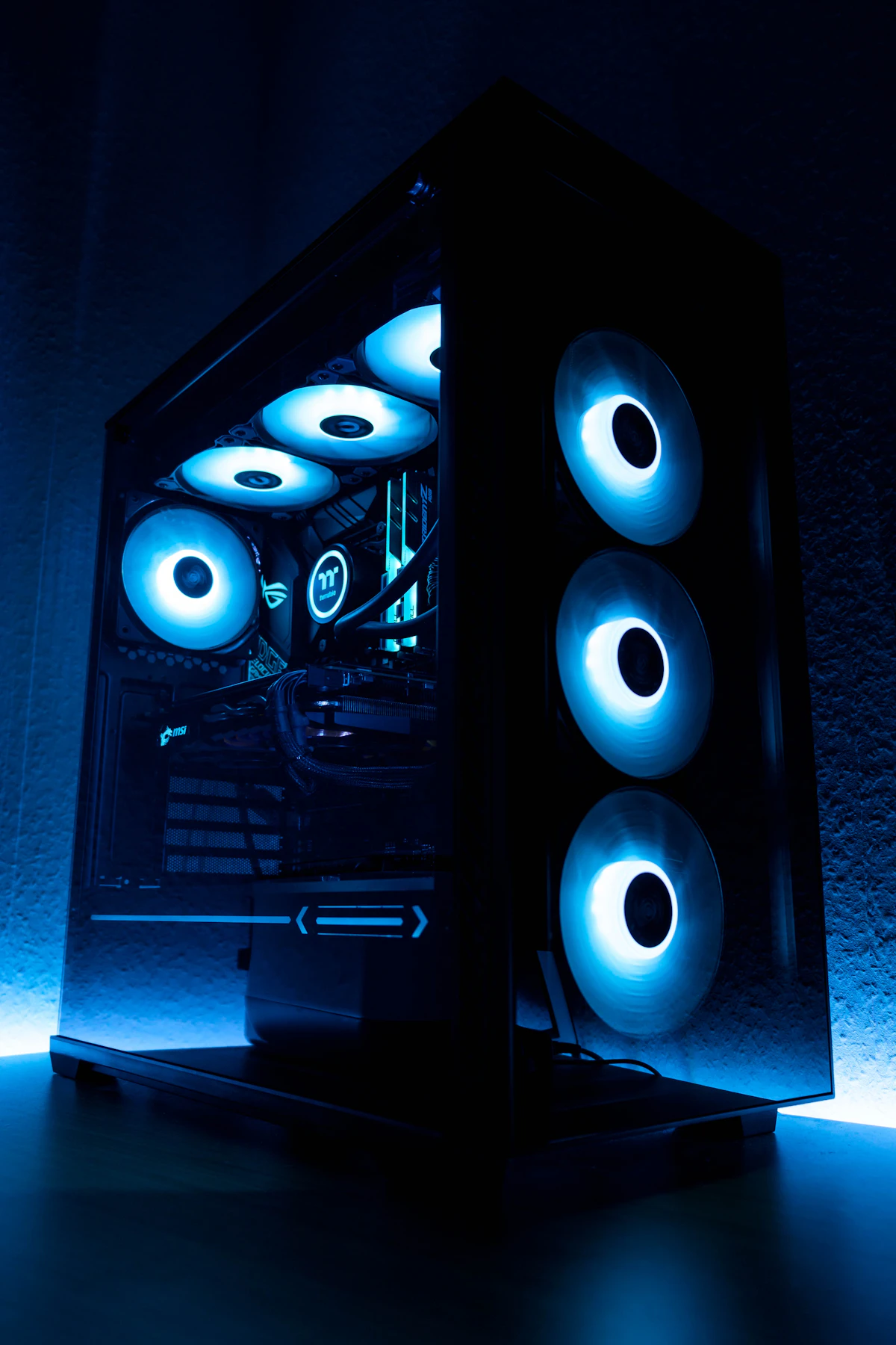
Step 1: Inspect PC Case Airflow and Fan Curves
Initially, check if warm exhaust air recirculates inside your PC enclosure. Modern high-wattage graphics cards demand positive case pressure and unrestricted intake paths.
Furthermore, launch MSI Afterburner to configure a custom fan response curve. Set fan speed to reach 75% output once core temperatures exceed 65°C, ensuring sufficient airflow passes through the heatsink fins before hotspot heat rapidly escalates.
Step 2: Clean Heatsink Fins and Shroud Assembly
Accumulated dust acts as a thermal insulator, blocking airflow across aluminum heatsink fins. Consequently, static pressure drops and heat builds around central contact plates.
Use compressed air or an electric duster while holding the fan blades still to avoid static electrical backfeeding into the PCB circuitry.
Step 3: Verify Physical PCIe Mounting and Sag
Heavy graphics cards experience mechanical sag when mounted horizontally. Over time, this gravitational pull unevenly pulls the copper cold-plate off the GPU die.
Therefore, install an anti-sag support bracket to realign contact pressure. If you need to re-seat or remove your card safely during maintenance, consult our step-by-step instructions on managing a Broken GPU PCIe Latch to prevent motherboard slot damage.
Advanced Solutions to Lower GPU Hotspot Temperature
When basic maintenance fails to resolve wide thermal deltas, direct intervention on the heatsink assembly is required. Modern direct-die cooling demands exact thermal interface materials (TIM).
Replacing Factory Thermal Paste with High-Viscosity TIM
Standard liquid thermal paste often suffers from the “pump-out effect.” As the GPU core expands and contracts under thermal cycles, thin paste pushes outward to the die edges, leaving bare silicon spots in the center.
To prevent this, apply thick, highly viscous compounds such as Thermal Grizzly Kryonaut Extreme or SYY-157. Alternatively, phase-change materials like Honeywell PTM7950 offer exceptional performance by turning solid at room temperature and liquid under load, effectively reducing your GPU Hotspot Temperature under load.
Replacing Thermal Pads and Correcting Thickness
Using incorrect thermal pad thickness during maintenance creates severe contact problems. For example, if VRAM or VRM thermal pads are even 0.5mm too thick, the main copper cold-plate cannot rest flush against the GPU die.
Always consult manufacturer mechanical schematics or community databases before replacing thermal pads. Alternatively, utilize viscous thermal putty (such as Upsiren U6 PRO), which automatically compresses to exact required tolerances under mounting pressure.
Re-Torque Spring Mounting Screws in X-Pattern
Uneven screw torque causes uneven contact across bare silicon dice. When securing the cooler backplate assembly, tighten screws using an incremental cross-pattern (top-left, bottom-right, top-right, bottom-left).
Specifically, turn each spring-loaded screw two full rotations at a time until finger-tight resistance is reached. This ensures pressure disperses symmetrically across the die surface.
Preventative Maintenance and Undervolting
Once mechanical contact issues are eliminated, software optimization prevents future thermal degradation. Software monitoring utilities like HWInfo allow real-time tracking of voltage, power draw, and junction sensor metrics.
Voltage Frequency Curve Tuning (Undervolting)
Modern graphics cards often supply excess core voltage out of the box to guarantee stability across all manufacturing silicon lottery variances. However, running lower operating voltages significantly reduces power consumption and overall heat generation.
Using MSI Afterburner, lock your core clock frequency to nominal boost specs (e.g., 1950 MHz) while reducing millivolt values from 1050mV down to 925mV–950mV range. Consequently, total board power drops by 40 to 60 watts with zero loss in gaming frame rate.
Routine Hardware Inspection Schedules
Finally, establish regular maintenance intervals every six to twelve months. Inspect dust filters, check fan bearing alignment, and verify board diagnostics. If your motherboard displays warning LEDs during startup following hardware remounting, read our complete guide on resolving the White VGA Light motherboard error.
By executing proper thermal paste selection, ensuring accurate mounting pressure, and tuning software voltages, maintaining a balanced GPU Hotspot Temperature ensures longevity and maximum graphics performance for years to come.
📺 Video Guide: How to Fix a GPU That's WAY TOO Hot 🥵🔥
Video walkthrough courtesy of Dedman Tech on YouTube. Follow along with the visual steps above.









[…] power or stability. Just as a healthy GPU is crucial for gaming performance (see our guide on GPU Hotspot Temperature), a stable power supply is vital for your Orbi […]
[…] TDR mechanism. This is particularly common in systems with inadequate cooling or heavy workloads. Monitoring GPU hotspot temperature is crucial for diagnosing thermal issues and preventing such […]